Antenna (radio)
An antenna (or aerial) is an electrical device which converts electric power into radio waves, and vice versa. It is usually used with a radio transmitter or radio receiver. In transmission, a radio transmitter supplies an oscillating radio frequency electric current to the antenna's terminals, and the antenna radiates the energy from the current as electromagnetic waves (radio waves). In reception, an antenna intercepts some of the power of an electromagnetic wave in order to produce a tiny voltage at its terminals, that is applied to a receiver to be amplified.
Antennas are essential components of all equipment that uses radio. They are used in systems such as radio broadcasting, broadcast television, two-way radio, communications receivers, radar, cell phones, and satellite communications, as well as other devices such as garage door openers, wireless microphones, bluetooth enabled devices, wireless computer networks, baby monitors, and RFID tags on merchandise.
Typically an antenna consists of an arrangement of metallic conductors ("elements"), electrically connected (often through a transmission line) to the receiver or transmitter. An oscillating current of electrons forced through the antenna by a transmitter will create an oscillating magnetic field around the antenna elements, while the charge of the electrons also creates an oscillating electric field along the elements. These time-varying fields, when created in the proper proportions, radiate away from the antenna into space as a moving transverse electromagnetic field wave. Conversely, during reception, the oscillating electric and magnetic fields of an incoming radio wave exert force on the electrons in the antenna elements, causing them to move back and forth, creating oscillating currents in the antenna.
Antennas may also include reflective or directive elements or surfaces not connected to the transmitter or receiver, such as parasitic elements, parabolic reflectors or horns, which serve to direct the radio waves into a beam or other desired radiation pattern. Antennas can be designed to transmit or receive radio waves in all directions equally (omnidirectional antennas), or transmit them in a beam in a particular direction, and receive from that one direction only (directional or high gain antennas).
The first antennas were built in 1888 by German physicist Heinrich Hertz in his pioneering experiments to prove the existence of electromagnetic waves predicted by the theory of James Clerk Maxwell. Hertz placed dipole antennas at the focal point of parabolic reflectors for both transmitting and receiving. He published his work in Annalen der Physik und Chemie (vol. 36, 1889).
Antennas are required by any radio receiver or transmitter to couple its electrical connection to the electromagnetic field. Radio waves are electromagnetic waves which carry signals through the air (or through space) at the speed of light with almost no transmission loss. Radio transmitters and receivers are used to convey signals (information) in systems including broadcast (audio) radio, television, mobile telephones, wi-fi (WLAN) data networks, trunk lines and point-to-point communications links (telephone, data networks), satellite links, many remote controlled devices such as garage door openers, and wireless remote sensors, among many others. Radio waves are also used directly for measurements in technologies including RADAR, GPS, and radio astronomy. In each and every case, the transmitters and receivers involved require antennas, although these are sometimes hidden (such as the antenna inside an AM radio or inside a laptop computer equipped with wi-fi).
According to their applications and technology available, antennas generally fall in one of two categories:
Omnidirectional or only weakly directional antennas which receive or radiate more or less in all directions. These are employed when the relative position of the other station is unknown or arbitrary. They are also used at lower frequencies where a directional antenna would be too large, or simply to cut costs in applications where a directional antenna isn't required.
Directional or beam antennas which are intended to preferentially radiate or receive in a particular direction or directional pattern.
In common usage "omnidirectional" usually refers to all horizontal directions, typically with reduced performance in the direction of the sky or the ground (a truly isotropic radiator is not even possible). A "directional" antenna usually is intended to maximize its coupling to the electromagnetic field in the direction of the other station, or sometimes to cover a particular sector such as a 120� horizontal fan pattern in the case of a panel antenna at a cell site.
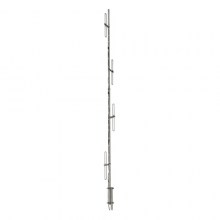
One example of omnidirectional antennas is the very common vertical antenna or whip antenna consisting of a metal rod (often, but not always, a quarter of a wavelength long). A dipole antenna is similar but consists of two such conductors extending in opposite directions, with a total length that is often, but not always, a half of a wavelength long. Dipoles are typically oriented horizontally in which case they are weakly directional: signals are reasonably well radiated toward or received from all directions with the exception of the direction along the conductor itself; this region is called the antenna blind cone or null.
Half-wave dipole antenna
Both the vertical and dipole antennas are simple in construction and relatively inexpensive. The dipole antenna, which is the basis for most antenna designs, is a balanced component, with equal but opposite voltages and currents applied at its two terminals through a balanced transmission line (or to a coaxial transmission line through a so-called balun). The vertical antenna, on the other hand, is a monopole antenna. It is typically connected to the inner conductor of a coaxial transmission line (or a matching network); the shield of the transmission line is connected to ground. In this way, the ground (or any large conductive surface) plays the role of the second conductor of a dipole, thereby forming a complete circuit.[5] Since monopole antennas rely on a conductive ground, a so-called grounding structure may be employed to provide a better ground contact to the earth or which itself acts as a ground plane to perform that function regardless of (or in absence of) an actual contact with the earth.
Antennas more complex than the dipole or vertical designs are usually intended to increase the directivity and consequently the gain of the antenna. This can be accomplished in many different ways leading to a plethora of antenna designs. The vast majority of designs are fed with a balanced line (unlike a monopole antenna) and are based on the dipole antenna with additional components (or elements) which increase its directionality. Antenna "gain" in this instance describes the concentration of radiated power into a particular solid angle of space, as opposed to the spherically uniform radiation of the ideal radiator. The increased power in the desired direction is at the expense of that in the undesired directions. Power is conserved, and there is no net power increase over that delivered from the power source (the transmitter.)
For instance, a phased array consists of two or more simple antennas which are connected together through an electrical network. This often involves a number of parallel dipole antennas with a certain spacing. Depending on the relative phase introduced by the network, the same combination of dipole antennas can operate as a "broadside array" (directional normal to a line connecting the elements) or as an "end-fire array" (directional along the line connecting the elements). Antenna arrays may employ any basic (omnidirectional or weakly directional) antenna type, such as dipole, loop or slot antennas. These elements are often identical.
However a log-periodic dipole array consists of a number of dipole elements of different lengths in order to obtain a somewhat directional antenna having an extremely wide bandwidth: these are frequently used for television reception in fringe areas. The dipole antennas composing it are all considered "active elements" since they are all electrically connected together (and to the transmission line). On the other hand, a superficially similar dipole array, the Yagi-Uda Antenna (or simply "Yagi"), has only one dipole element with an electrical connection; the other so-called parasitic elements interact with the electromagnetic field in order to realize a fairly directional antenna but one which is limited to a rather narrow bandwidth. The Yagi antenna has similar looking parasitic dipole elements but which act differently due to their somewhat different lengths. There may be a number of so-called "directors" in front of the active element in the direction of propagation, and usually a single (but possibly more) "reflector" on the opposite side of the active element.
ALMA array from the air[6]
Greater directionality can be obtained using beam-forming techniques such as a parabolic reflector or a horn. Since the size of a directional antenna depends on it being large compared to the wavelength, very directional antennas of this sort are mainly feasible at UHF and microwave frequencies. On the other hand, at low frequencies (such as AM broadcast) where a practical antenna must be much smaller than a wavelength, significant directionality isn't even possible. A vertical antenna or loop antenna small compared to the wavelength is typically used, with the main design challenge being that of impedance matching. With a vertical antenna a loading coil at the base of the antenna may be employed to cancel the reactive component of impedance; small loop antennas are tuned with parallel capacitors for this purpose.
An antenna lead-in is the transmission line (or feed line) which connects the antenna to a transmitter or receiver. The antenna feed may refer to all components connecting the antenna to the transmitter or receiver, such as an impedance matching network in addition to the transmission line. In a so-called aperture antenna, such as a horn or parabolic dish, the "feed" may also refer to a basic antenna inside the entire system (normally at the focus of the parabolic dish or at the throat of a horn) which could be considered the one active element in that antenna system. A microwave antenna may also be fed directly from a waveguide in lieu of a (conductive) transmission line.
An antenna counterpoise or ground plane is a structure of conductive material which improves or substitutes for the ground. It may be connected to or insulated from the natural ground. In a monopole antenna, this aids in the function of the natural ground, particularly where variations (or limitations) of the characteristics of the natural ground interfere with its proper function. Such a structure is normally connected to the return connection of an unbalanced transmission line such as the shield of a coaxial cable.
An electromagnetic wave refractor in some aperture antennas is a component which due to its shape and position functions to selectively delay or advance portions of the electromagnetic wavefront passing through it. The refractor alters the spatial characteristics of the wave on one side relative to the other side. It can, for instance, bring the wave to a focus or alter the wave front in other ways, generally in order to maximize the directivity of the antenna system. This is the radio equivalent of an optical lens.
An antenna coupling network is a passive network (generally a combination of inductive and capacitive circuit elements) used for impedance matching in between the antenna and the transmitter or receiver. This may be used to improve the standing wave ratio in order to minimize losses in the transmission line and to present the transmitter or receiver with a standard resistive impedance that it expects to see for optimum operation.
Basic antenna models
There are many variations of antennas. Below are a few basic models.
The isotropic radiator is a purely theoretical antenna that radiates equally in all directions. It is considered to be a point in space with no dimensions and no mass. This antenna cannot physically exist, but is useful as a theoretical model for comparison with all other antennas. Most antennas' gains are measured with reference to an isotropic radiator, and are rated in dBi (decibels with respect to an isotropic radiator).
The dipole antenna is simply two wires pointed in opposite directions arranged either horizontally or vertically, with one end of each wire connected to the radio and the other end hanging free in space. Since this is the simplest practical antenna, it is also used as a reference model for other antennas; gain with respect to a dipole is labeled as dBd. Generally, the dipole is considered to be omnidirectional in the plane perpendicular to the axis of the antenna, but it has deep nulls in the directions of the axis. Variations of the dipole include the folded dipole, the half wave antenna, the ground plane antenna, the whip, and the J-pole.
The Yagi-Uda antenna is a directional variation of the dipole with parasitic elements added which are functionality similar to adding a reflector and lenses (directors) to focus a filament light bulb.
The random wire antenna is simply a very long (at least one quarter wavelength[citation needed]) wire with one end connected to the radio and the other in free space, arranged in any way most convenient for the space available. Folding will reduce effectiveness and make theoretical analysis extremely difficult. (The added length helps more than the folding typically hurts.) Typically, a random wire antenna will also require an antenna tuner, as it might have a random impedance that varies non-linearly with frequency.
The horn antenna is used where high gain is needed, the wavelength is short (microwave) and space is not an issue. Horns can be narrow band or wide band, depending on their shape. A horn can be built for any frequency, but horns for lower frequencies are typically impractical. Horns are also frequently used as reference antennas.
The parabolic antenna consists of an active element at the focus of a parabolic reflector to reflect the waves into a plane wave. Like the horn it is used for high gain, microwave applications, such as satellite dishes.
The patch antenna consists mainly of a square conductor mounted over a groundplane. Another example of a planar antenna is the tapered slot antenna (TSA), as the Vivaldi-antenna.
Radio antenna theory
Ground plane
In telecommunication, a ground plane is a flat or nearly flat horizontal conducting surface that serves as part of an antenna, to reflect the radio waves from the other antenna elements. The plane does not necessarily have to be connected to ground. Ground planes are particularly used with monopole antennas.
To function as a ground plane, the conducting surface must be at least a quarter of the wavelength (λ/4) of the radio waves in size. In lower frequency antennas, such as the mast radiators used for broadcast antennas, the Earth itself (or a body of water such as a salt marsh or ocean) is used as a ground plane. For higher frequency antennas, in the VHF or UHF range, the ground plane can be smaller, and metal disks, screens or wires are used as ground planes. At upper VHF and UHF frequencies, the metal skin of a car or aircraft can serve as a ground plane for whip antennas projecting from it. The ground plane doesn't have to be a continuous surface. In the ground plane antenna the "plane" consists of several wires λ/4 long radiating from the base of a quarter wave whip antenna.
The radio waves from an antenna element that reflect off a ground plane appear to come from a mirror image of the antenna located on the other side of the ground plane. In a monopole antenna, the radiation pattern of the monopole plus the virtual "image antenna" make it appear as a two element center-fed dipole antenna. So a monopole mounted over an ideal ground plane has a radiation pattern identical to a dipole antenna. The feedline from the transmitter or receiver is connected between the bottom end of the monopole element and the ground plane. The ground plane must have good conductivity; any resistance in the ground plane is in series with the antenna, and serves to dissipate power from the transmitter.
It is a fundamental property of antennas that the electrical characteristics of an antenna described in the next section, such as gain, radiation pattern, impedance, bandwidth, resonant frequency and polarization, are the same whether the antenna is transmitting or receiving.[7][8] For example, the "receiving pattern" (sensitivity as a function of direction) of an antenna when used for reception is identical to the radiation pattern of the antenna when it is driven and functions as a radiator. This is a consequence of the reciprocity theorem of electromagnetics.[8] Therefore in discussions of antenna properties no distinction is usually made between receiving and transmitting terminology, and the antenna can be viewed as either transmitting or receiving, whichever is more convenient.
A necessary condition for the aforementioned reciprocity property is that the materials in the antenna and transmission medium are linear and reciprocal. Reciprocal (or bilateral) means that the material has the same response to an electric current or magnetic field in one direction, as it has to the field or current in the opposite direction. Most materials used in antennas meet these conditions, but some microwave antennas use high-tech components such as isolators and circulators, made of nonreciprocal materials such as ferrite.[7][8] These can be used to give the antenna a different behavior on receiving than it has on transmitting,[7] which can be useful in applications like radar.
Parameters
Antennas are characterized by a number of performance measures which a user would be concerned with in selecting or designing an antenna for a particular application. Chief among these relate to the directional characteristics (as depicted in the antenna's radiation pattern) and the resulting gain. Even in omnidirectional (or weakly directional) antennas, the gain can often be increased by concentrating more of its power in the horizontal directions, sacrificing power radiated toward the sky and ground. The antenna's power gain (or simply "gain") also takes into account the antenna's efficiency, and is often the primary figure of merit.
Resonant antennas are expected to be used around a particular resonant frequency; an antenna must therefore be built or ordered to match the frequency range of the intended application. A particular antenna design will present a particular feedpoint impedance. While this may affect the choice of an antenna, an antenna's impedance can also be adapted to the desired impedance level of a system using a matching network while maintaining the other characteristics (except for a possible loss of efficiency).
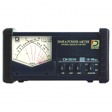
Although these parameters can be measured in principle, such measurements are difficult and require very specialized equipment. Beyond tuning a transmitting antenna using an SWR meter, the typical user will depend on theoretical predictions based on the antenna design or on claims of a vendor.
An antenna transmits and receives radio waves with a particular polarization which can be reoriented by tilting the axis of the antenna in many (but not all) cases. The physical size of an antenna is often a practical issue, particularly at lower frequencies (longer wavelengths). Highly directional antennas need to be significantly larger than the wavelength. Resonant antennas use a conductor, or a pair of conductors, each of which is about one quarter of the wavelength in length. Antennas that are required to be very small compared to the wavelength sacrifice efficiency and cannot be very directional. Fortunately at higher frequencies (UHF, microwaves) trading off performance to obtain a smaller physical size is usually not required.
Resonant antennas
While there are broadband designs for antennas, the vast majority of antennas are based on the half-wave dipole which has a particular resonant frequency. At its resonant frequency, the wavelength (figured by dividing the speed of light by the resonant frequency) is slightly over twice the length of the half-wave dipole (thus the name). The quarter-wave vertical antenna consists of one arm of a half-wave dipole, with the other arm replaced by a connection to ground or an equivalent ground plane (or counterpoise). A Yagi-Uda array consists of a number of resonant dipole elements, only one of which is directly connected to the transmission line. The quarter-wave elements of a dipole or vertical antenna imitate a series-resonant electrical element, since if they are driven at the resonant frequency a standing wave is created with the peak current at the feed-point and the peak voltage at the far end.
A common misconception is that the ability of a resonant antenna to transmit (or receive) fails at frequencies far from the resonant frequency. The reason a dipole antenna needs to be used at the resonant frequency has to do with the impedance match between the antenna and the transmitter or receiver (and its transmission line). For instance, a dipole using a fairly thin conductor[9] will have a purely resistive feedpoint impedance of about 63 ohms at its design frequency. Feeding that antenna with a current of 1 ampere will require 63 volts of RF, and the antenna will radiate 63 watts (ignoring losses) of radio frequency power. If that antenna is driven with 1 ampere at a frequency 20% higher, it will still radiate as efficiently but in order to do that about 200 volts would be required due to the change in the antenna's impedance which is now largely reactive (voltage out of phase with the current). A typical transmitter would not find that impedance acceptable and would deliver much less than 63 watts to it; the transmission line would be operating at a high (poor) standing wave ratio. But using an appropriate matching network, that large reactive impedance could be converted to a resistive impedance satisfying the transmitter and accepting the available power of the transmitter.
This principle is used to construct vertical antennas substantially shorter than the 1/4 wavelength at which the antenna is resonant. By adding an inductance in series with the vertical antenna (a so-called loading coil) the capacitative reactance of this antenna can be cancelled leaving a pure resistance which can then be matched to the transmission line. Sometimes the resulting resonant frequency of such a system (antenna plus matching network) is described using the construct of "electrical length" and the use of a shorter antenna at a lower frequency than its resonant frequency is termed "electrical lengthening". For example, at 30 MHz (wavelength = 10 meters) a true resonant monopole would be almost 2.5 meters (1/4 wavelength) long, and using an antenna only 1.5 meters tall would require the addition of a loading coil. Then it may be said that the coil has "lengthened" the antenna to achieve an "electrical length" of 2.5 meters, that is, 1/4 wavelength at 30 MHz where the combined system now resonates. However, the resulting resistive impedance achieved will be quite a bit lower than the impedance of a resonant monopole, likely requiring further impedance matching. In addition to a lower radiation resistance, the reactance becomes higher as the antenna size is reduced, and the resonant circuit formed by the antenna and the tuning coil has a Q factor that rises and eventually causes the bandwidth of the antenna to be inadequate for the signal being transmitted. This is the major factor that sets the size of antennas at 1 MHz and lower frequencies.
Gain
In electronics, gain is a measure of the ability of a circuit (often an amplifier) to increase the power or amplitude of a signal from the input to the output, by adding energy to the signal converted from some power supply. It is usually defined as the mean ratio of the signal output of a system to the signal input of the same system. It may also be defined on a logarithmic scale, in terms of the decimal logarithm of the same ratio ("dB gain"). A gain greater than one (zero dB), that is, amplification, is the defining property of an active component or circuit, while a passive circuit will have a gain of less than one.
Thus, the term gain on its own is ambiguous. For example, "a gain of five" may imply that either the voltage, current or the power(wattage) is increased by a factor of five, although most often this will mean a voltage gain of five for audio and general purpose amplifiers, especially operational amplifiers, but a power gain for radio frequency amplifiers. Furthermore, the term gain is also applied in systems such as sensors where the input and output have different units; in such cases the gain units must be specified, as in "5 microvolts per photon" for the responsivity of a photosensor. The "gain" of a bipolar transistor normally refers to forward current transfer ratio, either hFE ("Beta", the static ratio of Ic divided by Ib at some operating point), or sometimes hfe (the small-signal current gain, the slope of the graph of Ic against Ib at a point).
The term has slightly different meanings in two other fields. In antenna design, antenna gain is the ratio of power received by a directional antenna to power received by an isotropic antenna. In laser physics, gain may refer to the increment of power along the beam propagation direction in a gain medium, and its dimension is m−1 (inverse meter) or 1/meter.
Logarithmic units and decibels
Power gain
Power gain, in decibels (dB), is defined by the 10 log rule as follows:
where Pin and Pout are the input and output powers respectively.
A similar calculation can be done using a natural logarithm instead of a decimal logarithm, and without the factor of 10, resulting in nepers instead of decibels:
Voltage gain
When power gain is calculated using voltage instead of power, making the substitution (P=V 2/R), the formula is:

In many cases, the input and output impedances are equal, so the above equation can be simplified to:

and then the 20 log rule:
This simplified formula is used to calculate a voltage gain in decibels, and is equivalent to a power gain only if the impedances at input and output are equal.
Current gain
In the same way, when power gain is calculated using current instead of power, making the substitution (P = I 2R), the formula is:

In many cases, the input and output impedances are equal, so the above equation can be simplified to:

and then:
This simplified formula is used to calculate a current gain in decibels, and is equivalent to the power gain only if the impedances at input and output are equal.
The "current gain" of a bipolar transistor, hFE or hfe, is normally given as a dimensionless number, the ratio of Ic to Ib (or slope of the Ic-versus-Ib graph, for hfe).
In the cases above, gain will be a dimensionless quantity, as it is the ratio of like units (Decibels are not used as units, but rather as a method of indicating a logarithmic relationship). In the bipolar transistor example it is the ratio of the output current to the input current, both measured in Amperes. In the case of other devices, the gain will have a value in SI units. Such is the case with the operational transconductance amplifier, which has an open-loop gain (transconductance) in Siemens (mhos), because the gain is a ratio of the output current to the input voltage.
Example
Q. An amplifier has an input impedance of 50 ohms and drives a load of 50 ohms. When its input (![]() ) is 1 volt, its output (
) is 1 volt, its output (![]() ) is 10 volts. What is its voltage and power gain?
) is 10 volts. What is its voltage and power gain?
A. Voltage gain is simply:
The units V/V are optional, but make it clear that this figure is a voltage gain and not a power gain. Using the expression for power, P = V2/R, the power gain is:
Again, the units W/W are optional. Power gain is more usually expressed in decibels, thus:
A gain of factor 1 (equivalent to 0 dB) where both input and output are at the same voltage level and impedance is also known as unity gain.
Current and voltage distribution
The antenna conductors have the lowest feed-point impedance at the resonant frequency where they are just under 1/4 wavelength long; two such conductors in line fed differentially thus realizes the familiar "half-wave dipole". When fed with an RF current at the resonant frequency, the quarter wave element contains a standing wave with the voltage and current largely (but not exactly) in phase quadrature, as would be obtained using a quarter wave stub of transmission line. The current reaches a minimum at the end of the element (where it has nowhere to go!) and is maximum at the feed-point. The voltage, on the other hand, is the greatest at the end of the conductor and reaches a minimum (but not zero) at the feedpoint. Making the conductor shorter or longer than 1/4 wavelength means that the voltage pattern reaches its minimum somewhere beyond the feed-point, so that the feed-point has a higher voltage and thus sees a higher impedance, as we have noted. Since that voltage pattern is almost in phase quadrature with the current, the impedance seen at the feed-point is not only much higher but mainly reactive.
It can be seen that if such an element is resonant at f0 to produce such a standing wave pattern, then feeding that element with 3f0 (whose wavelength is 1/3 that of f0) will lead to a standing wave pattern in which the voltage is likewise a minimum at the feed-point (and the current at a maximum there). Thus, an antenna element is also resonant when its length is 3/4 of a wavelength (3/2 wavelength for a complete dipole). This is true for all odd multiples of 1/4 wavelength, where the feed-point impedance is purely resistive, though larger than the resistive impedance of the 1/4 wave element. Although such an antenna is resonant and works perfectly well at the higher frequency, the antenna radiation pattern is also altered compared to the half-wave dipole.
The use of a monopole or dipole at odd multiples of the fundamental resonant frequency, however, does not extend to even multiples (thus a 1/2 wavelength monopole or 1 wavelength dipole). Now the voltage standing wave is at its peak at the feed-point, while that of the current (which must be zero at the end of the conductor) is at a minimum (but not exactly zero). The antenna is anti-resonant at this frequency. Although the reactance at the feedpoint can be cancelled using such an element length, the feed-point impedance is very high, and is highly dependent on the diameter of the conductor (which makes only a small difference at the actual resonant frequency). Such an antenna does not match the much lower characteristic impedance of available transmission lines, and is generally not used. However some equipment where transmission lines are not involved which desire a high driving point impedance may take advantage of this anti-resonance.
Bandwidth
Although a resonant antenna has a purely resistive feed-point impedance at a particular frequency, many (if not most) applications require using an antenna over a range of frequencies. An antenna's bandwidth specifies the range of frequencies over which its performance does not suffer due to a poor impedance match. Also in the case of a Yagi-Uda array, the use of the antenna very far away from its design frequency reduces the antenna's directivity, thus reducing the usable bandwidth regardless of impedance matching.
Except for the latter concern, the resonant frequency of a resonant antenna can always be altered by adjusting a suitable matching network. To do this efficiently one would require remotely adjusting a matching network at the site of the antenna, since simply adjusting a matching network at the transmitter (or receiver) would leave the transmission line with a poor standing wave ratio.
Instead, it is often desired to have an antenna whose impedance does not vary so greatly over a certain bandwidth. It turns out that the amount of reactance seen at the terminals of a resonant antenna when the frequency is shifted, say, by 5%, depends very much on the diameter of the conductor used. A long thin wire used as a half-wave dipole (or quarter wave monopole) will have a reactance significantly greater than the resistive impedance it has at resonance, leading to a poor match and generally unacceptable performance. Making the element using a tube of a diameter perhaps 1/50 of its length, however, results in a reactance at this altered frequency which is not so great, and a much less serious mismatch which will only modestly damage the antenna's net performance. Thus rather thick tubes are typically used for the solid elements of such antennas, including Yagi-Uda arrays.
Rather than just using a thick tube, there are similar techniques used to the same effect such as replacing thin wire elements with cages to simulate a thicker element. This widens the bandwidth of the resonance. On the other hand, amateur radio antennas need to operate over several bands which are widely separated from each other. This can often be accomplished simply by connecting resonant elements for the different bands in parallel. Most of the transmitter's power will flow into the resonant element while the others present a high (reactive) impedance and draw little current from the same voltage. A popular solution uses so-called traps consisting of parallel resonant circuits which are strategically placed in breaks along each antenna element. When used at one particular frequency band the trap presents a very high impedance (parallel resonance) effectively truncating the element at that length, making it a proper resonant antenna. At a lower frequency the trap allows the full length of the element to be employed, albeit with a shifted resonant frequency due to the inclusion of the trap's net reactance at that lower frequency.
The bandwidth characteristics of a resonant antenna element can be characterized according to its Q, just as one uses to characterize the sharpness of an L-C resonant circuit. However it is often assumed that there is an advantage in an antenna having a high Q. After all, Q is short for "quality factor" and a low Q typically signifies excessive loss (due to unwanted resistance) in a resonant L-C circuit. However this understanding does not apply to resonant antennas where the resistance involved is the radiation resistance, a desired quantity which removes energy from the resonant element in order to radiate it (the purpose of an antenna, after all!). The Q is a measure of the ratio of reactance to resistance, so with a fixed radiation resistance (an element's radiation resistance is almost independent of its diameter) a greater reactance off-resonance corresponds to the poorer bandwidth of a very thin conductor. The Q of such a narrowband antenna can be as high as 15. On the other hand a thick element presents less reactance at an off-resonant frequency, and consequently a Q as low as 5. These two antennas will perform equivalently at the resonant frequency, but the second antenna will perform over a bandwidth 3 times as wide as the "hi-Q" antenna consisting of a thin conductor.
Effective area or aperture
The effective area or effective aperture of a receiving antenna expresses the portion of the power of a passing electromagnetic wave which it delivers to its terminals, expressed in terms of an equivalent area. For instance, if a radio wave passing a given location has a flux of 1 pW / m2 (10−12 watts per square meter) and an antenna has an effective area of 12 m2, then the antenna would deliver 12 pW of RF power to the receiver (30 microvolts rms at 75 ohms). Since the receiving antenna is not equally sensitive to signals received from all directions, the effective area is a function of the direction to the source.
Due to reciprocity (discussed above) the gain of an antenna used for transmitting must be proportional to its effective area when used for receiving. Consider an antenna with no loss, that is, one whose electrical efficiency is 100%. It can be shown that its effective area averaged over all directions must be equal to λ2/4π, the wavelength squared divided by 4π. Gain is defined such that the average gain over all directions for an antenna with 100% electrical efficiency is equal to 1. Therefore the effective area Aeff in terms of the gain G in a given direction is given by:
A_{eff} = {\lambda^2 \over 4 \pi} \, G
For an antenna with an efficiency of less than 100%, both the effective area and gain are reduced by that same amount. Therefore the above relationship between gain and effective area still holds. These are thus two different ways of expressing the same quantity. Aeff is especially convenient when computing the power that would be received by an antenna of a specified gain, as illustrated by the above example.
Radiation pattern
The radiation pattern of an antenna is a plot of the relative field strength of the radio waves emitted by the antenna at different angles. It is typically represented by a three dimensional graph, or polar plots of the horizontal and vertical cross sections. The pattern of an ideal isotropic antenna, which radiates equally in all directions, would look like a sphere. Many nondirectional antennas, such as monopoles and dipoles, emit equal power in all horizontal directions, with the power dropping off at higher and lower angles; this is called an omnidirectional pattern and when plotted looks like a torus or donut.
The radiation of many antennas shows a pattern of maxima or "lobes" at various angles, separated by "nulls", angles where the radiation falls to zero. This is because the radio waves emitted by different parts of the antenna typically interfere, causing maxima at angles where the radio waves arrive at distant points in phase, and zero radiation at other angles where the radio waves arrive out of phase. In a directional antenna designed to project radio waves in a particular direction, the lobe in that direction is designed larger than the others and is called the "main lobe". The other lobes usually represent unwanted radiation and are called "sidelobes". The axis through the main lobe is called the "principal axis" or "boresight axis".
Field regions
The space surrounding an antenna can be divided into three concentric regions: the reactive near-field, the radiating near-field (Fresnell region) and the far-field (Fraunhofer) regions. These regions are useful to identify the field structure in each, although there are no precise boundaries.
In the far-field region, we are far enough from the antenna to neglect its size and shape. We can assume that the electromagnetic wave is purely a radiating plane wave (electric and magnetic fields are in phase and perpendicular to each other and to the direction of propagation). This simplifies the mathematical analysis of the radiated field.
Impedance
As an electro-magnetic wave travels through the different parts of the antenna system (radio, feed line, antenna, free space) it may encounter differences in impedance (E/H, V/I, etc.). At each interface, depending on the impedance match, some fraction of the wave's energy will reflect back to the source,[11] forming a standing wave in the feed line. The ratio of maximum power to minimum power in the wave can be measured and is called the standing wave ratio (SWR). A SWR of 1:1 is ideal. A SWR of 1.5:1 is considered to be marginally acceptable in low power applications where power loss is more critical, although an SWR as high as 6:1 may still be usable with the right equipment. Minimizing impedance differences at each interface (impedance matching) will reduce SWR and maximize power transfer through each part of the antenna system.
Complex impedance of an antenna is related to the electrical length of the antenna at the wavelength in use. The impedance of an antenna can be matched to the feed line and radio by adjusting the impedance of the feed line, using the feed line as an impedance transformer. More commonly, the impedance is adjusted at the load (see below) with an antenna tuner, a balun, a matching transformer, matching networks composed of inductors and capacitors, or matching sections such as the gamma match.
Antenna efficiency
Efficiency of a transmitting antenna is the ratio of power actually radiated (in all directions) to the power absorbed by the antenna terminals. The power supplied to the antenna terminals which is not radiated is converted into heat. This is usually through loss resistance in the antenna's conductors, but can also be due to dielectric or magnetic core losses in antennas (or antenna systems) using such components. Such loss effectively robs power from the transmitter, requiring a stronger transmitter in order to transmit a signal of a given strength.
For instance, if a transmitter delivers 100 W into an antenna having an efficiency of 80%, then the antenna will radiate 80 W as radio waves and produce 20 W of heat. In order to radiate 100 W of power, one would need to use a transmitter capable of supplying 125 W to the antenna. Note that antenna efficiency is a separate issue from impedance matching, which may also reduce the amount of power radiated using a given transmitter. If an SWR meter reads 150 W of incident power and 50 W of reflected power, that means that 100 W have actually been absorbed by the antenna (ignoring transmission line losses). How much of that power has actually been radiated cannot be directly determined through electrical measurements at (or before) the antenna terminals, but would require (for instance) careful measurement of field strength. Fortunately the loss resistance of antenna conductors such as aluminum rods can be calculated and the efficiency of an antenna using such materials predicted.
However loss resistance will generally affect the feedpoint impedance, adding to its resistive (real) component. That resistance will consist of the sum of the radiation resistance Rr and the loss resistance Rloss. If an rms current I is delivered to the terminals of an antenna, then a power of I2Rr will be radiated and a power of I2Rloss will be lost as heat. Therefore the efficiency of an antenna is equal to Rr / (Rr + Rloss). Of course only the total resistance Rr + Rloss can be directly measured.
According to reciprocity, the efficiency of an antenna used as a receiving antenna is identical to the efficiency as defined above. The power that an antenna will deliver to a receiver (with a proper impedance match) is reduced by the same amount. In some receiving applications, the very inefficient antennas may have little impact on performance. At low frequencies, for example, atmospheric or man-made noise can mask antenna inefficiency. For example, CCIR Rep. 258-3 indicates man-made noise in a residential setting at 40 MHz is about 28 dB above the thermal noise floor. Consequently, an antenna with a 20 dB loss (due to inefficiency) would have little impact on system noise performance. The loss within the antenna will affect the intended signal and the noise/interference identically, leading to no reduction in signal to noise ratio (SNR).
This is fortunate, since antennas at lower frequencies which are not rather large (a good fraction of a wavelength in size) are inevitably inefficient (due to the small radiation resistance Rr of small antennas). Most AM broadcast radios (except for car radios) take advantage of this principle by including a small loop antenna for reception which has an extremely poor efficiency. Using such an inefficient antenna at this low frequency (530�1650 kHz) thus has little effect on the receiver's net performance, but simply requires greater amplification by the receiver's electronics. Contrast this tiny component to the massive and very tall towers used at AM broadcast stations for transmitting at the very same frequency, where every percentage point of reduced antenna efficiency entails a substantial cost.
The definition of antenna gain or power gain already includes the effect of the antenna's efficiency. Therefore if one is trying to radiate a signal toward a receiver using a transmitter of a given power, one need only compare the gain of various antennas rather than considering the efficiency as well. This is likewise true for a receiving antenna at very high (especially microwave) frequencies, where the point is to receive a signal which is strong compared to the receiver's noise temperature. However in the case of a directional antenna used for receiving signals with the intention of rejecting interference from different directions, one is no longer concerned with the antenna efficiency, as discussed above. In this case, rather than quoting the antenna gain, one would be more concerned with the directive gain which does not include the effect of antenna (in)efficiency. The directive gain of an antenna can be computed from the published gain divided by the antenna's efficiency.
Polarization (waves)
The polarization of an antenna is the orientation of the electric field (E-plane) of the radio wave with respect to the Earth's surface and is determined by the physical structure of the antenna and by its orientation. It has nothing in common with antenna directionality terms: "horizontal", "vertical", and "circular". Thus, a simple straight wire antenna will have one polarization when mounted vertically, and a different polarization when mounted horizontally. "Electromagnetic wave polarization filters"[citation needed] are structures which can be employed to act directly on the electromagnetic wave to filter out wave energy of an undesired polarization and to pass wave energy of a desired polarization.
Reflections generally affect polarization. For radio waves the most important reflector is the ionosphere - signals which reflect from it will have their polarization changed unpredictably. For signals which are reflected by the ionosphere, polarization cannot be relied upon. For line-of-sight communications for which polarization can be relied upon, it can make a large difference in signal quality to have the transmitter and receiver using the same polarization; many tens of dB difference are commonly seen and this is more than enough to make the difference between reasonable communication and a broken link.
Polarization is largely predictable from antenna construction but, especially in directional antennas, the polarization of side lobes can be quite different from that of the main propagation lobe. For radio antennas, polarization corresponds to the orientation of the radiating element in an antenna. A vertical omnidirectional WiFi antenna will have vertical polarization (the most common type). An exception is a class of elongated waveguide antennas in which vertically placed antennas are horizontally polarized. Many commercial antennas are marked as to the polarization of their emitted signals.
Polarization is the sum of the E-plane orientations over time projected onto an imaginary plane perpendicular to the direction of motion of the radio wave. In the most general case, polarization is elliptical, meaning that the polarization of the radio waves varies over time. Two special cases are linear polarization (the ellipse collapses into a line) and circular polarization (in which the two axes of the ellipse are equal). In linear polarization the antenna compels the electric field of the emitted radio wave to a particular orientation. Depending on the orientation of the antenna mounting, the usual linear cases are horizontal and vertical polarization. In circular polarization, the antenna continuously varies the electric field of the radio wave through all possible values of its orientation with regard to the Earth's surface. Circular polarizations, like elliptical ones, are classified as right-hand polarized or left-hand polarized using a "thumb in the direction of the propagation" rule. Optical researchers use the same rule of thumb, but pointing it in the direction of the emitter, not in the direction of propagation, and so are opposite to radio engineers' use.
In practice, regardless of confusing terminology, it is important that linearly polarized antennas be matched, lest the received signal strength be greatly reduced. So horizontal should be used with horizontal and vertical with vertical. Intermediate matchings will lose some signal strength, but not as much as a complete mismatch. Transmitters mounted on vehicles with large motional freedom commonly use circularly polarized antennas[citation needed] so that there will never be a complete mismatch with signals from other sources.
Impedance matching